
Creating an HMI in CODESYS
Introduction
Until now I’ve used OpenPLC for all my PLC (ladder logic) projects, as it’s very user-friendly and it makes using an Arduino as a PLC very simply. However, as I was studying LL and ST, another piece of software kept being mentioned - CODESYS.
According to CODESYS, they are “the leading manufacturer-independent IEC 61131-3 automation software for engineering control systems”. Compared with OpenPLC, it is much more feature-rich (and more complex), able to interface with a large number of PLCs. However, the reason I was interested in it is for one particular feature it has that OpenPLC doesn’t - you can make your own basic HMI (human-machine interfaces) with it.
Learning CODESYS
This video series, although a few years old, is very good for covering the basics in a short, concise manner.
Playlist: https://www.youtube.com/playlist?list=PLimc0qc7y0tQ0aZnk3d9rkLUAUnJ-sLzv
First video, which covers LL and HMI:
Temperature Control HMI
In OpenPLC I had a steady(ish) state project (both LL) which turned on a heater or cooler based on the value of a sensor - the idea being, in a very simple way, to keep the temperature between 60° and 70°, perfect for your cup of tea or coffee.
I thought I’d use this same project (in ST form) as a way to experiment with creating an HMI with CODESYS.
Code
Copying the code was easy enough. No change needed.
IF sensor >= temp_max THEN
  cooler_on := TRUE;
  heater_on := FALSE;
  ideal_temp := FALSE;
END_IF;

IF sensor <= temp_min THEN
  heater_on := TRUE;
  cooler_on := FALSE;
  ideal_temp := FALSE;
END_IF;

IF sensor <= temp_max AND sensor >= temp_min THEN
  ideal_temp := TRUE;
  IF sensor < perfect_temp THEN
    heater_on := TRUE;
    cooler_on := FALSE;
  END_IF;
  IF sensor > perfect_temp THEN
    cooler_on := TRUE;
    heater_on := FALSE;
  END_IF;
  IF sensor = perfect_temp THEN
    cooler_on := FALSE;
    heater_on := FALSE;
  END_IF;
END_IF;
Variables
Where OpenPLC has a table at the top for the variables, CODESYS has them in code form. Constant variables are defined/initialised separately. But, still, it’s pretty simple.
PROGRAM PLC_PRG
VAR CONSTANT
	perfect_temp: INT := 65;
	temp_min: INT := 60;
	temp_max: INT := 70;
END_VAR
VAR
	sensor: INT;
	cooler_on: BOOL;
	heater_on: BOOL;
	ideal_temp: BOOL;
END_VAR
Note that as this isn’t being transferred to run on an Arduino with the 16-bit analogue input, we can forget the strange values; instead we can simply use the ideal ones of 60, 65, and 70.
HMI
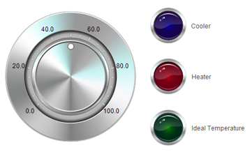
The videos linked to above explain how to create the HMI. I used a potentiometer to simulate the sensor, then three lights to simulate the outputs - a blue light for the cooler, a red light for the heater, and a green light for when your cup of tea or coffee is within the ideal temperature range.
Simulation
Once it’s all in place, you can build, log in, and debug (again, explained in the above videos), and then we get something that looks like this.
Pretty cool! Note how the values appear live in the code, and the variables table, and are reflected in the HMI, which would make debugging more advanced projects much simpler than with OpenPLC.
Comments?
Feel free to comment on my LinkedIn post.